Since the CoolBot first arrived on the market in 2006, growers and others within the produce community have been finding creative ways to develop on-farm cooling that are both effective and affordable. The relatively low cost of AC unit-based cooling as well as reduced power demands during cycling also allow growers to build mobile coolers from heavily-insulated box trailers. Researchers at the Plants for Human Health Institute at North Carolina State University published information about the Pack ‘N Cool Mobile Cooler, which has been instrumental in leading the rapid adoption of mobile coolers since 2012.
For many small and/or urban farmers growing in the Central United States, cooling facilities are a still a major barrier due to the high cost of traditional walk-in coolers and limited access to existing ones, particularly for first-generation growers. A large-scale survey of local produce growers surrounding Kansas City in 2014 revealed that access to proper storage facilities, especially cold storage, is one of the most frequently-encountered challenges for producers to scale-up local food production.
With this information, Kansas State University and the Kansas Department of Agriculture partnered through a Specialty Crop Block Grant to build a mobile cooler for grower demonstration and education. The grant project was led by Eleni Pliakoni and other Horticulture and Food Science faculty at KSU, and the cooler was built by students and staff at the KSU Olathe Horticulture Research and Extension Center. This article provides considerations for its components as well as a how-to guide to build a similar one.

Many uses for the KoolCat
Although the mobile cooling unit was originally conceived to be able to take products to market at a low cost, it has several other uses as well:
Traditional (stationary) cold storage
Use on harvest days for fragile products like small fruit and greens
Transportation of products to wholesale customers
Temporary cold storage at roadside stands and U-Pick operations
Curing and storing crops through the winter
Limitations of the KoolCat
Needs a level area with enough space to park and load plus electricity (if used as stationary cooler)
Will bounce more than a truck on bumpy roads
CoolBot system does not provide control over relative humidity
Considerations for building the KoolCat
The Trailer – For the trailer dimensions, we chose to build a larger cooler using a 6’ x 12’, dual-axle box trailer with a square(ish) front end. After insulation was installed, the resulting inside dimensions of the cooler are approximately 5’ x 11’, which allow ample room for 2-3 pallets or bins with circulation airspace around the products. Although the larger sized, dual-axle trailer is more expensive than a smaller one, the second axle significantly increases the capacity of the cooler for heavier crops like tomatoes, melons, and sweet potatoes. The KoolCat can fit over 120 bushel boxes, which would weigh more than 6000 lbs if loaded with tomatoes. The weight capacity of the two axles is 7000 lbs (5500 lbs payload) as opposed to 3500 lbs for a single axle. So it’s much less likely to overload the capacity of the axles when filled with heavy produce. When determining weight capacity, don’t forget that the insulation and AC unit weigh approximately 500 lbs combined.
An unexpected advantage of the second axle is cooler stability. At the research station in Olathe, the KoolCat is used as the primary cooler to store crops from vegetable research trials that are typically donated or distributed to staff and it remains stationary when not in use for workshops and demonstrations. The second axle allows staff to load and work in the cooler while not attached to a vehicle with little to no chance of “see-sawing”, which is particularly helpful if using it for daily cold storage on the farm.
Insulation – Structurally Insulated Panels (SIPs) were chosen for the insulation and were available locally as reclaimed materials. SIPs have closed cell foam and therefore retain their R-value better in moist conditions than many of the foam insulation options available at the hardware store. When moisture permeates open cell foam insulation like expanded polystyrene (XPS and EPS) and polyurethane foam, it can lose 20-80% of its R-Value in a single year. This could potentially reduce the lifespan of the cooler dramatically during wet or humid conditions.
The SIPs for the KoolCat have a painted metal skin on either side, and are therefore compliant as a washable surface. The SIPs also eliminate the need for wooden framing or paneling, which minimizes the chance for rotting or other structural issues within the cooler due to moisture. They also had tongue-and-groove assembly, making it simpler to connect and assemble the panels together. Ten, 4’x10’ panels were used to make the KoolCat, which were 6” thick and have an estimated R-Value of greater than 30.
Cooling – A CoolBot unit along with a 10,000 BTU window air conditioner was utilized for the KoolCat. Specifications for the air conditioner were provided by the CoolBot team at https://www.storeitcold.com/, which also provides how-to guides for mobile coolers and other helpful information for on-farm storage.
This diagram shows the order of construction of the KoolCat: front, floor, sides, cieling, and finally the addition of the refrigeration unit. All images by the author unless otherwise noted.
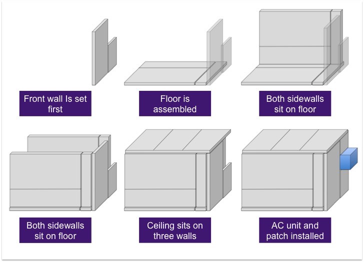
KoolCat construction
One of the challenges for mobile coolers is minimizing the negative effects of moisture on the structure of the trailer. All non-essential wood components were removed and the remaining wooden floor decking and door panels of the trailer were painted with heavy-duty, moisture-resistant paint (e.g. KILZ) before the cooler was assembled.
Wiring for the outlets and switches was installed so that outlet boxes could be mounted into the SIPs. A 14-gauge extension cord was used as the pigtail and was fished through the trailer frame and into the front of the trailer floor where it was connected into internal wiring in a junction box. The junction box also held the outlet for the AC Unit and CoolBot in the front of the cooler. The internal wiring was routed to the rear of the cooler for switched lights in addition to an extra outlet near the cooler doors.
When installing electrical wires in a trailer, care should be taken to stabilize any wires where they penetrate through metal to prevent slicing of the wires from vibration or movement, which could lead to electrical shorts or potential danger from electrocution. Wire mounts can be purchased from hardware stores or trailer supply stores that stabilize the wire in the hole of the junction box or metal skin of the SIPs and prevent damage to the wire. To install the boxes into the SIPs, use “old work” junction and/or electrical boxes that have tabs, which secure the box to the metal skin from behind. This style of box is designed for installation in houses without removing or disturbing the drywall.
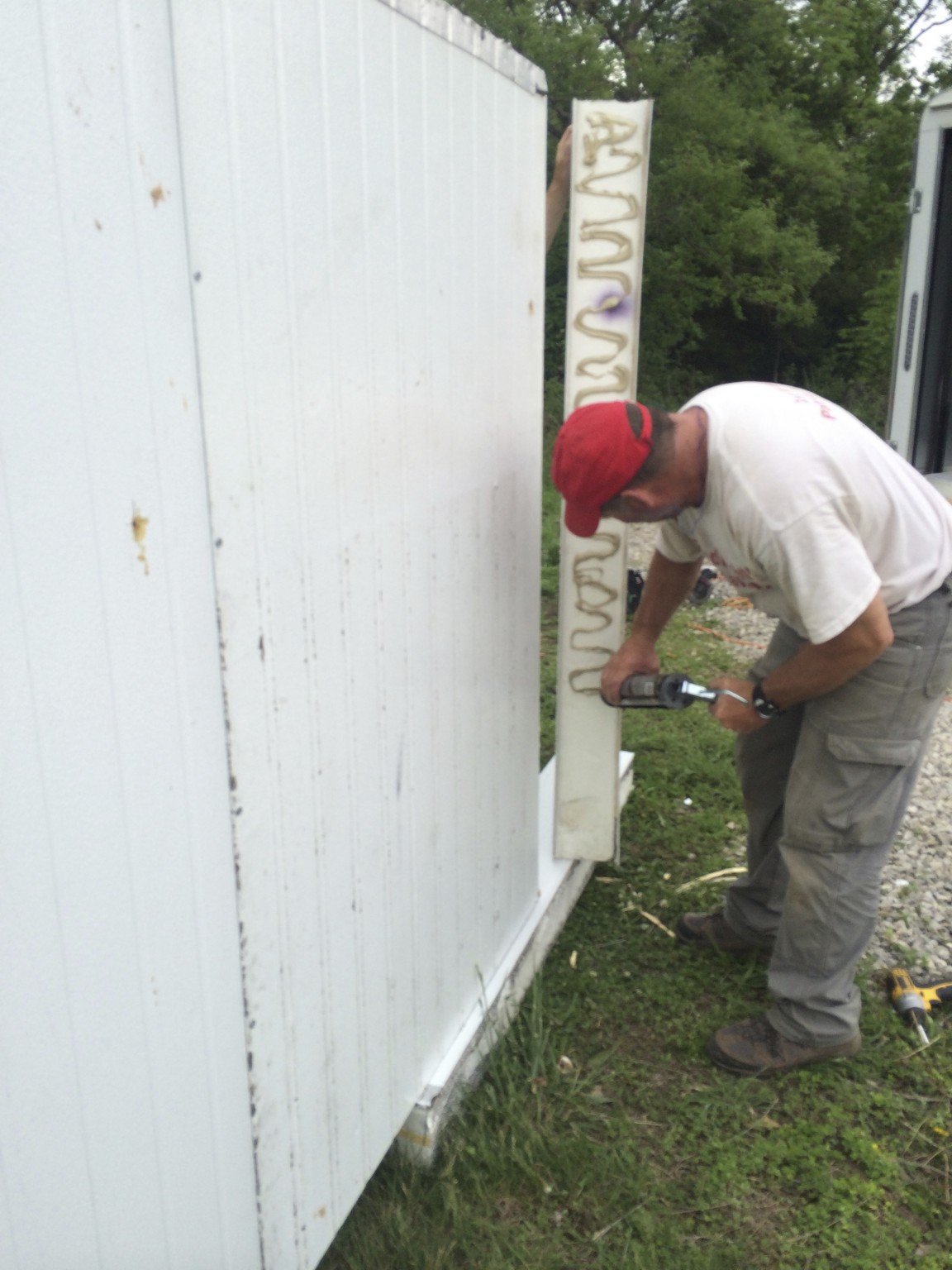
Next the panels were measured and cut before assembly. A diagram is provided to illustrate the arrangement of the ten, 4’ x 10’ SIPs. The individual panels were assembled into the walls, floor, and ceiling prior to being installed into the trailer. The SIPs were cut with a 5” counter rotating blade circular saw. Once the metal skin was cut on both sides, a hand saw was used to cut the foam between the metal skins. The tongue-and-groove fittings attached with construction adhesive and self-tapping metal screws to hold together the foam and metal outer layers, respectively. Be sure to always wear eye protection when cutting or drilling into metal.
Below, the front wall and floor are set first. The opening at the front should be wide enough to fit the AC unit, 6” of insulation, and whatever airspace may exist outside the insulation. Photo by Lani Meyer.
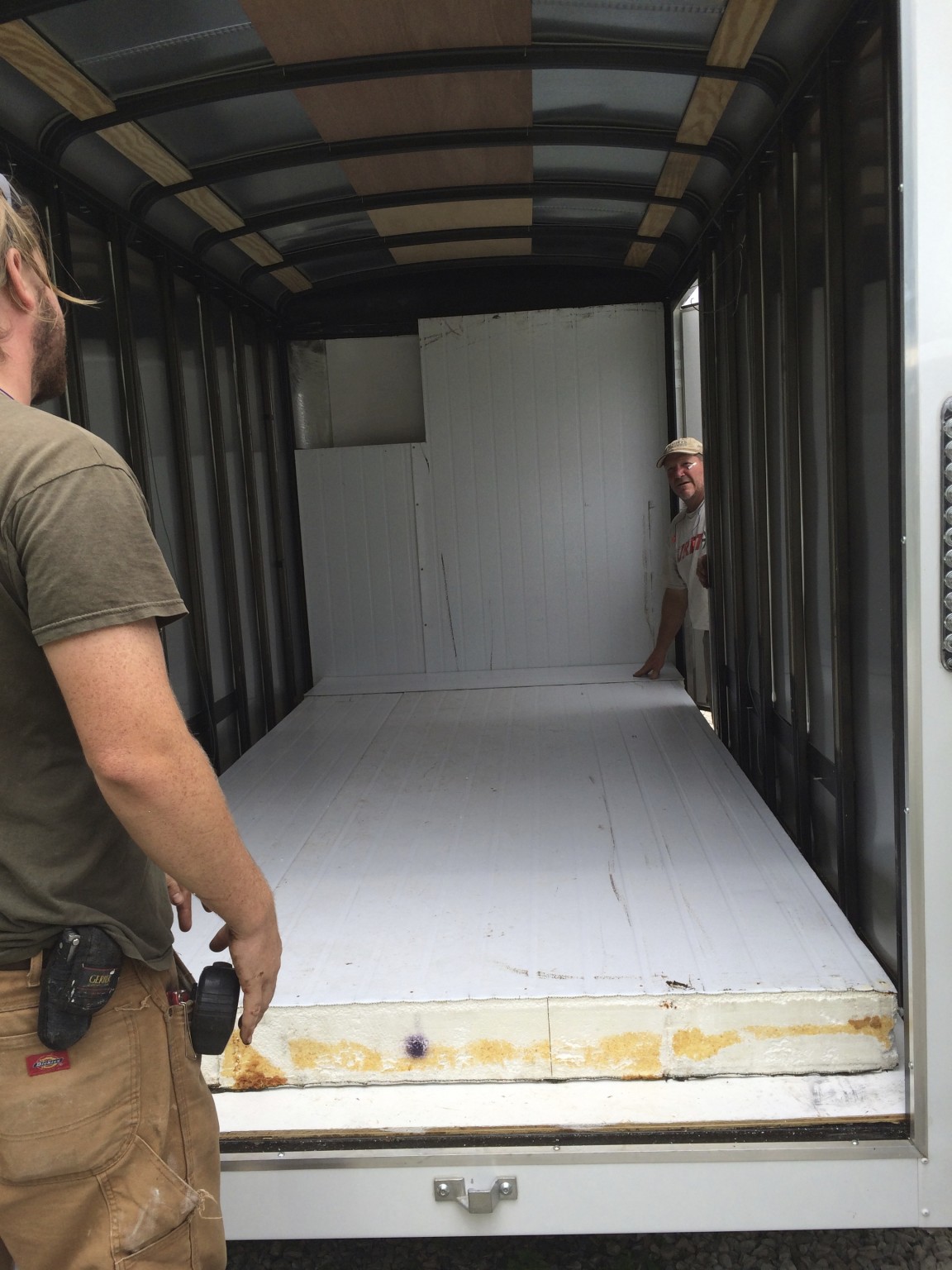
The front wall of insulation was cut to fit the AC unit, which was set to one side. There was a supporting rib of the trailer in the center and cutting this rib for AC placement would have been detrimental to its structure. In our case, we waited to cut the hole in the trailer for the AC unit until after the SIPs were assembled and we knew its exact location. The outer metal layer was cut slightly below (1/4”) the inside layer underneath the location of the AC unit in order to tilt it enough for water to drain out during operation and the foam was subsequently cut at an angle.
Because the front wall of the trailer was slightly rounded, wooden blocking was used to support the front wall of insulation in the center. Next, the cooler floor was assembled from two SIPs and laid down up against the front wall. The sidewalls were then assembled, as well as the ceiling outside the trailer. The top of the ceiling panels were notched due to the location of trailer support ribs that were not square at the corners. Because the ceiling panel would need to be slid into place to be supported by the front wall, the notches were approximately 3” wider than the support ribs towards the back of the cooler.
Installing the ceiling and walls into the trailer was the most physically difficult part of the project and requires at least 3-4 people to lift and manipulate the panels into place. The ceiling panels were supported by the edges of the walls, but the trailer would not allow it to be slid in from the rear due to the size of the door opening. The passenger side wall was set vertically against the wall of the trailer and would remain in this position.
Below, both side walls were assembled and checked for clearance so that the ceiling panel had room to sit on top. Photo by Lani Meyer.
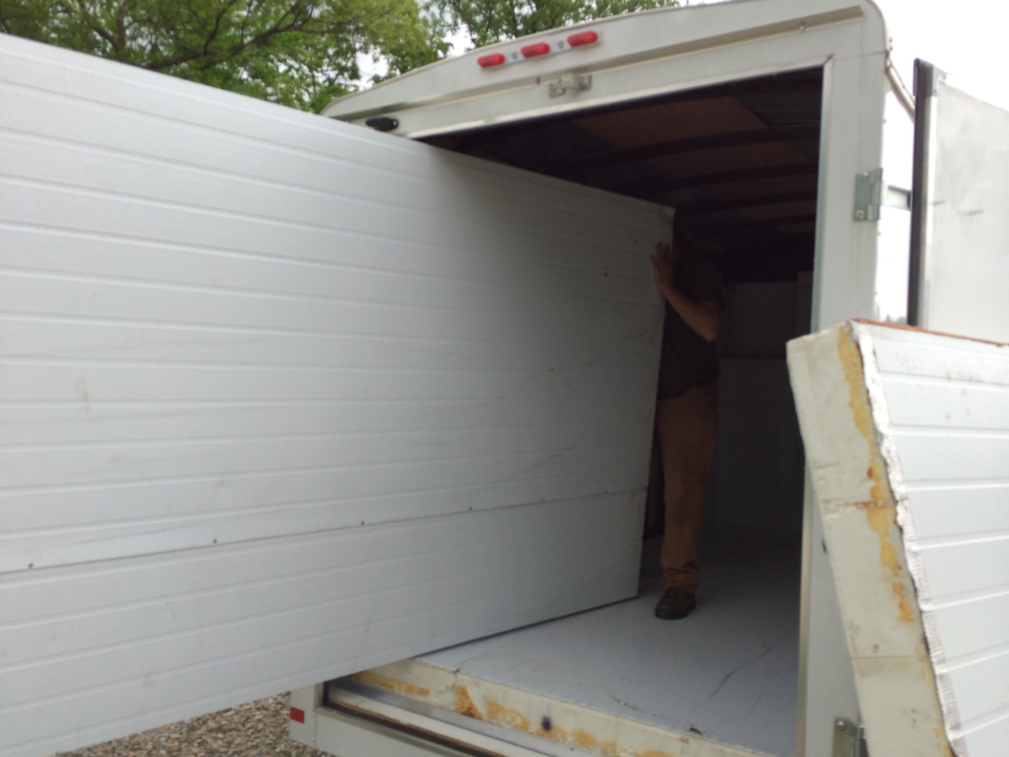
Next the ceiling was angled into the trailer so that the edge was supported by the passenger side wall at the top. The ceiling was then slid forward into place so that it was supported on the front edge by the insulation and it was even with the ends of the floor panels below. While the ceiling panel was held, the driver side wall was brought into the trailer at an angle so that the bottom was against the trailer wall and the top was leaning towards the passenger side. Finally, the top of the driver side panel was pushed towards the trailer wall until it was fully upright and supporting the ceiling.
Once the cooler was assembled in the trailer, the hole was cut for the AC unit in the trailer with the counter rotating blade circular saw. The AC unit was installed and the final piece of panel was cut and held with metal brackets above the unit. Plastic lumber (1” x 4”) was used to frame the AC unit and firmly secure it into place at an angle to keep water draining out of the cooler during operation. The plastic lumber was attached to the SIPs with 2” self-tapping metal screws.
Right, the SIPs were assembled with construction adhesive and self-tapping screws at the tongue and groove joints. All three photos by Lani Meyer.
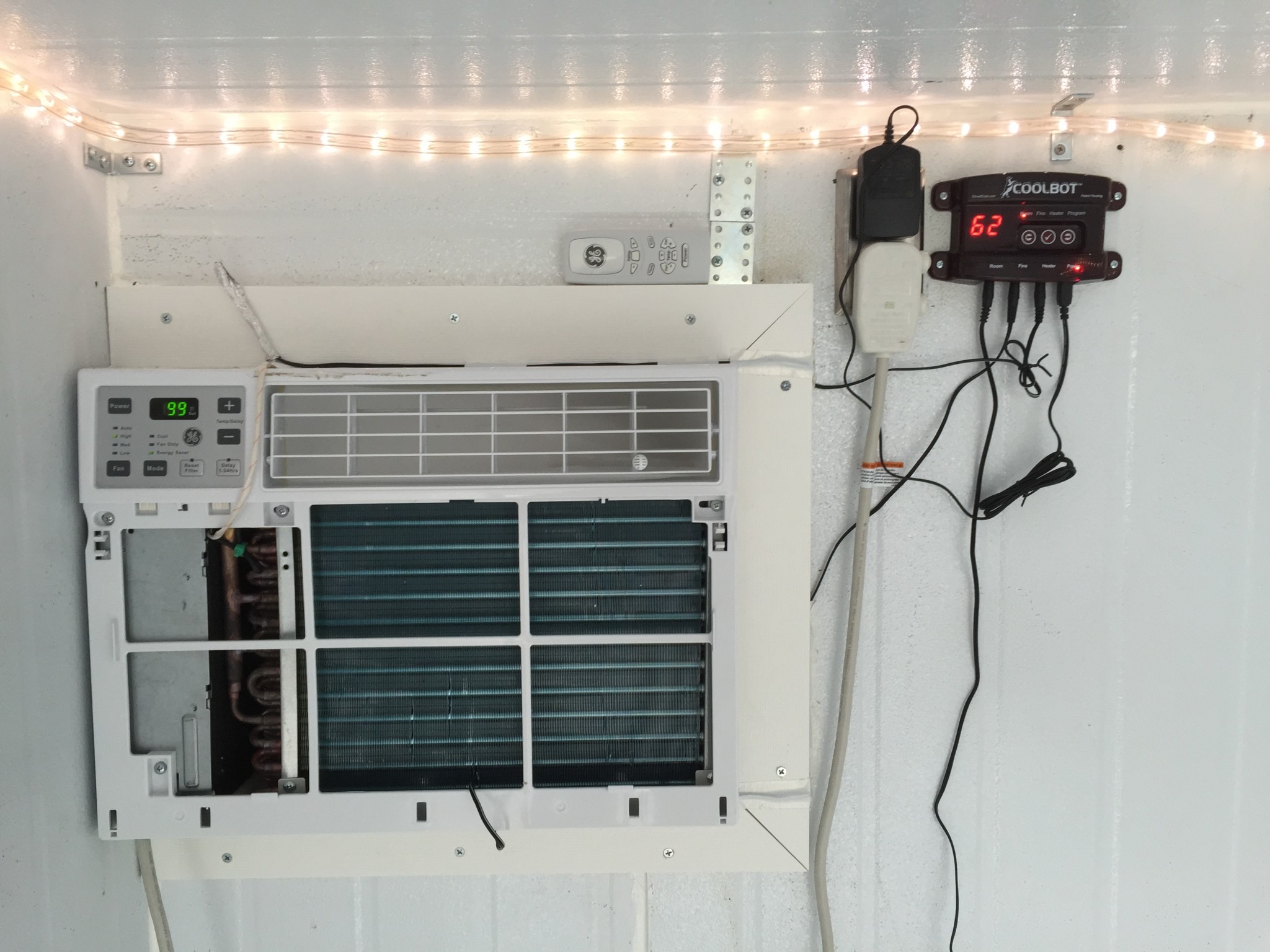
The CoolBot was then mounted and installed on the AC unit using the directions provided by the manufacturer. Once the insulation was installed in the trailer, 2” right angle brackets were installed with self-tapping metal screws to keep the wall, floor, and ceiling panels from moving during transport and potential shifting over time. The electrical work was completed and the two outlets and a switch were installed as well as gasketed cover plates to prevent infiltration by moisture. Although a GFCI outlet was not installed in the trailer, we utilize one for the supplying power outlet to the cooler and this is recommended to prevent damage or electrical shock.
Insulation was added to the rear doors so that the panels would be pushed in behind the floor panel when closed. The SIPs were mounted to the door by replacing three of the bolts on each door that were used for the hinges and latch with much longer bolts (4”). A nut was installed to hold the bolt in its original place and then the remainder of the long bolt could be used to fasten the panel to the door. Holes were drilled through the insulation and a hex coupler was threaded onto the bolt approximately halfway. Then, the panels were lifted into place and a (1-2”) bolt and washer was threaded into the hex coupler and tightened to hold the insulation. The picture shows the hardware without the insulation in place to demonstrate the pieces that are needed and their final assembly.
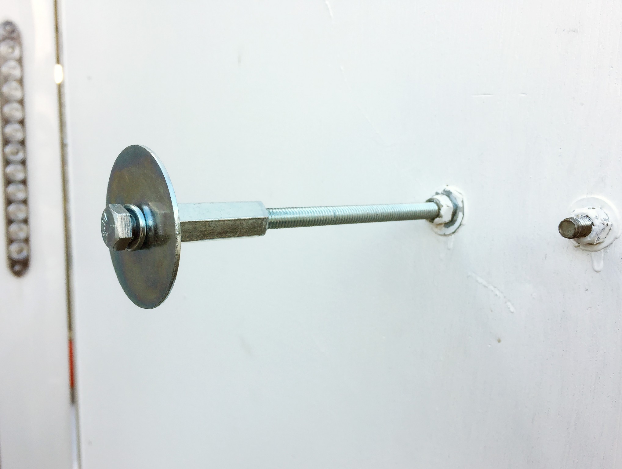
Above is a detail of the hardware used to mount the 6” insulated panels to the trailer doors. One bolt was replaced at each hinge and one at the latch for each door.
Once all the insulation was in place, all cracks and joints were sealed with weatherproof caulking. Rope lighting was mounted in the upper corner along the sides and front of the cooler for additional convenience. Trim was added at the ends of the panels to protect the insulation and prevent cuts and scrapes from the sharp edges of the metal. Rubber batting was glued to the foam to prevent any moisture from accumulating on the foam, and drywall corner bead was used to secure the batting and provide a smooth edge for the metal. Aluminum angle (1” x 1/16” thick) was used to trim the corners of the floor panel and is considerably more durable than the drywall bead to foot traffic.
Weather stripping was added around the door opening and was attached with weatherproof adhesive as well as small self-tapping screws with finishing washers. Around the ceiling and walls of the opening, garage door bottom seal was mounted to the cooler just inside the back end so as to seal any gap(s) around the door when it was shut. White EPDM cellular rubber weather-strip tape was added towards the bottom of the door panels to seal the gap between the door and floor. Anti-slip tape was also added to the first “step” of the cooler for traction.
Below is the final installation of AC Unit, CoolBot, and rope lighting.
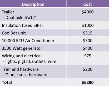
Cost of Materials
The total estimated material cost for the mobile cooling unit was $6290. We did not accurately track labor, but estimated that it took approximately 5 days with two skilled workers assembling the trailer components. Of the total cost, 64% was the trailer. In our case, the SIPs were available from reclaimed materials and our costs for the used panels were much lower than new ones. All other components other than the CoolBot unit were available for purchase at the local hardware supply company.
The author thanks Jacob Chapman, Brian Boutte, Mike Ryan, Lani Meyer, and the Olathe Horticulture Research and Extension Center for their contributions to the project. Funding for the KoolCat was provided by a Kansas Department of Agriculture Specialty Crop Block Grant.
Cary Rivard is an Extension Specialist and Assistant Professor in the Department of Horticulture and Natural Resources at Kansas State University. He is located at the Olathe Horticulture Research and Extension Center where he also serves as the Center Director.

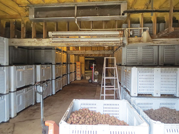 This article outlines designing and building a facility for long-term vegetable storage. A well-designed storage facility enables you to store high-quality vegetables many months after harvesting and thus access lucrative markets starved for local produce during the winter.